전기화학적 수소발생반응을 위한 카본 페이퍼 위 NiCoS의 펄스 전기전착
Pulse electrodeposition of NiCoS on carbon paper for electrochemical hydrogen evolution reaction
Article information
Trans Abstract
NiCoS has good conductivity, and the sulfur it contains is known to improve the activity for hydrogen evolution reaction. Thus NiCoS has recently attracted much attention as a catalyst for hydrogen evolution reaction catalyst in neutral-pH water electrolysis. In this study, NiCoS was fabricated using pulse electrodeposition method and the effect of off time on the composition, morphology, and hydrogen evolution reaction activity was investigated. The physical and chemical characteristics of the catalyst were analyzed using field emission scanning electron microscopy, X-ray diffractometry, electrochemical impedance spectroscopy, etc. It was observed that the surface area of NiCoS, the sulfur content, and hydrogen evolution reaction activity of NiCoS increased together as the off time increased at a constant on time. The NiCoS with the highest sulfur content, produced by pulse electrodeposition, showed overpotentials of 262 and 285 mV to deliver current densities of 10, 50 mA/cm2, respectively, in the neutral pH region.
1. 서론
지구온난화 문제가 점점 심각해짐에 따라 온실가스 감축의 중요성이 대두되고 있다. 이에 2015년 기후변화 대응을 위해 국제 협약인 파리협정에서 주요 온실가스 배출국들은 오는 2030년까지 온실가스 배출량을 25~60%까지 감축하겠다고 공언했다. 그리고 배출량 감축에 대한 대책으로 대부분의 국가는 화석에너지 중심 사회에서 신재생에너지 중심 사회로의 전환을 주요 목표로 내걸고 있다. 수소는 신재생에너지 시스템에 있어서 에너지 저장 및 운송 시 기존 화석연료를 대신할 물질로 가장 많은 관심을 받고 있다[1, 2]. 이에 수소를 생산하는 방법도 많은 연구가 이루어지고 있는데, 그중에서 물을 전기 분해하여 수소를 생산하는 수전해가 하나의 방법으로 여겨지고 있다. 특히, 신재생에너지 기반의 수전해는 기존 화석연료 기반의 수증기 개질 방식보다 친환경적일 뿐만 아니라, 생성된 수소의 순도도 높아서 수전해와 관련해서 다양한 연구가 이루어지고 있다[3, 4].
하지만 보편적인 수소 생산 방법으로 수전해를 이용하기 위해서는 아직 여러 기술적인 문제점들을 해결해야 하며, 그중 수전해에 사용되는 촉매의 비싼 가격은 수전해 기술의 보편화에 큰 걸림돌이 되고 있다. 수전해에서는 수소발생반응(hydrogen evolution reaction; HER)이 일어나는 환원극과, 산소발생반응(oxygen evolution reaction)이 일어나는 산화극으로 구성되는데, 이때 이 두 전극에 사용되는 촉매의 가격이 상당히 높은 편이다. 특히 HER 에서 사용되는 대표적 촉매인 백금(Pt)은 희소성이 높고 가격이 매우 비싸다는 단점 때문에 수전해 상용화의 큰 걸림돌로 작용해왔다[5, 6]. 이러한 문제를 해결하기 위해 지구에 풍부하고 저렴한 전이금속 기반의 다양한 대체 촉매에 대한 연구가 계속 진행되고 있다[7].
NiCoS는 대표적인 전이금속 기반의 HER 촉매이다. NiCoS는 bimetal 구조로 NiS, CoS 보다 우수한 전도도를 가지고 있다[8, 9]. 뿐만 아니라, NiCoS 내 구조적인 결함 형성과 합금 형성을 통한 표면 전하 밀도 변화를 이용해 HER에 대한 활성 증가 효과를 얻을 수 있다. 그래서, 일반적으로 CoS, NiS보다 NiCoS가 HER 촉매로서 더 우수한 활성을 나타낸다[10]. 또한 전기 음성도가 높은 황(S)은, 촉매 표면에 수소를 흡착하는데 필요한 에너지를 감소시키고 활성점으로도 작용하기 때문에 NiCoS는 HER 촉매로도 많은 연구가 이루어지고 있다[11,12].
NiCoS 촉매 합성에는 여러 가지 방법이 존재한다. 수열합성(hydrothermal synthesis), 전기전착(electrodeposition), 화학기상증착(chemical vapor deposition) 등이 있다[13]. 이 중에서 전기전착은 다른 촉매 합성 방식과 달리 상온, 상압 조건에서 진행할 수 있어 에너지 소모가 적을 뿐만 아니라, 큰 규모의 스케일에도 적용이 가능하다는 장점을 가지고 있다[14, 15]. 그리고 기판 위에 직접 촉매를 형성할 수 있어서 촉매를 기판에 고정하는 별도의 과정이 필요 없는 binder-free 방법 중 하나이기도 하다[16]. 또한 전기화학적 매개변수 조절을 통해 다양한 조건에서 촉매를 합성할 수 있다는 것도 전기전착의 장점이다[17, 18]. 때문에 NiCoS 촉매도 이러한 전기전착으로 합성하는 연구가 몇몇 보고된 바 있다[19–21]. 하지만 대부분의 경우, 전기전착 시 일정 전류나 전압을 인가하거나 순환전류전압법(cyclic voltammetry; CV) 등의 단순한 방법으로 NiCoS 촉매를 합성하였다. 본 연구에서는 펄스 전기전착법(pulse electrodeposition)을 이용하여 NiCoS 촉매를 제작하고, 펄스 전기전착법 조건 변화가 형성된 NiCoS 촉매에 미치는 영향을 조사하였다. 펄스 전기전착법은 전류 또는 전압을 인가하는 기간(on time; T on)과 인가하지 않는 기간(off time; T off)으로 구성된 사이클을 이용하는 방식으로, T on과 T off를 조절하여 전기전착되는 물질의 형상과 성질을 변화시킬 수 있다[22, 23]. 특히 T off 동안 전극 인근의 확산층(diffusion layer)에 반응 물질을 공급할 수 있는 점은 펄스 전기전착의 큰 장점이다. 때문에 이 방법은 촉매 합성뿐만 아니라 전자회로 분야에서도 많이 사용되고 있다[24, 25]. 본 연구에서는 펄스 전기전착의 T off 이 NiCoS 촉매의 조성과 구조에 어떠한 영향을 미치는지 중점적으로 관찰하고, 이러한 영향이 NiCoS 의 HER 활성과 어떤 연관성이 있는지 조사하였다.
2. 실험방법
2.1. NiCoS의 펄스 전기전착
촉매가 전착되는 기판으로는 carbon paper(2 cm2, Spectracarb 2050A-1550)를 사용하였으며, 기판 위의 이물질을 제거하기 위해 아세톤에서 5분 동안 sonication 한 후, 탈 이온수로 세척하였다. NiCoS 의 전기전착은 3전극계(3-electrode system)에서 수행하였다. 작업전극(working electrode)과 상대전극(counter electrode)은 각각 carbon paper와 Pt sheet(1 cm2, Metrohm)전극을 사용하였고, 기준전극(reference electrode)으로는 Ag/AgCl(3 M KCl, Metrohm)을 사용하였다. NiCoS 전기전착이 이루어지는 전해질은 3 mM NiCl2 · 6 H2 O(99.3%, Sigma-Aldrich), 2 mM CoCl2 · 6 H2 O(≥95.0%, Sigma-Aldrich)와 150 mM의 thiourea(SC(NH2)2, 99%, Sigma-Aldrich)로 구성되었다. 이 때 thiourea는 황의 전구체로 사용하였다.
모든 실험은 정전위기(AUTOLAB PGSTAT302N, Metrohm)를 이용해 진행하였다 (Fig. 1). 펄스 전기전착은 −1.8 V (vs. Ag/AgCl)를 인가하는 T on과 전위를 인가하지 않는 T off로 사이클을 구성하였으며, 이때 T on 은 0.5 초로 일정하게 고정시켰다. 전착 전압(−1.8 V)은 정전위법(constant-potential deposition)에서 가장 우수한 HER 활성을 나타낸 NiCoS를 기준으로 정하였다. 이후 T off를 각각 0.1, 0.5, 1, 2, 4 초로 설정하여 T off가 NiCoS의 제작에 미치는 영향을 살펴보았다. NiCoS의 전착량을 일정하게 유지하기 위하여 전위를 인가하는 전체 시간은 200 초로 설정하여 T off로 인한 영향만을 관찰하고자 하였으며, T off의 시간에 따라 제작된 각각의 시료를 NiCoS-0.1, 0.5, 1, 2, 4라고 명명하였다 (Table 1). 그리고 대조군으로 정전위법으로 전착된 NiCoS 시료(NiCoS-CP)를 함께 준비하였다. 정전위법에서도 동일하게 −1.8 V (vs. Ag/AgCl)에서 전착을 진행하였으며, 전착 시간은 200 초로 설정하였다. 제작한 모든 시료들은 탈이온수로 세척한 이후 질소 가스를 이용해 건조하였다. 모든 실험은 상온에서 진행되었다.
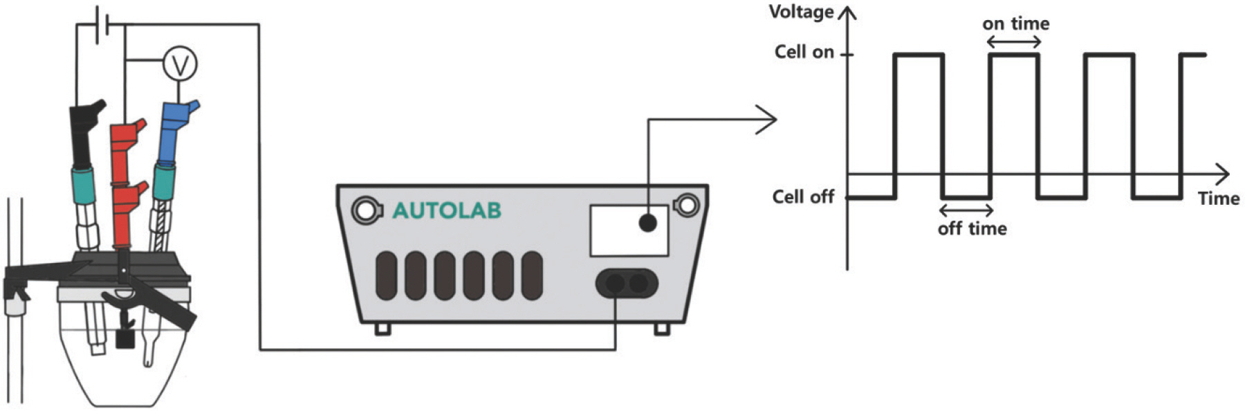
Schematic of NiCoS pulse electrodeposition system.

List of NiCoS samples prepared by pulse electrode position
2.2. 촉매의 특성 분석
NiCoS 시료의 형상과 화학적 조성은 에너지 분산형 분광분석법(Energy Dispersive X-ray Spectroscopy; EDS)이 가능한 전계 방출형 주사전자현미경(Field Emission Scanning Electron Microscope; FE-SEM, Germini 300, ZEISS)을 이용하여 분석하였다. 그리고 X선 회절분석기(X-ray diffractometer, XRD; D2 phaser, Bruker)를 통해 각 시료의 결정구조를 분석하였으며, X선(Cu Kα)은 0.032°/s 의 주사 속도로 2θ = 20 – 80°의 범위에서 조사하였다.
2.3. NiCoS 시료의 전기화학적 평가
NiCoS 시료의 HER 활성 및 내구성 평가를 비롯한 전기 이중층 캐패시터 (double-layer capacitance, C dl,) 측정, 전기화학 임피던스 분광법 (electrochemical impedance spectroscopy, EIS) 은 모두 1 M의 인산완충용액(phosphate buffered solution; PBS) 용액에서 진행하였다. 1M PBS는 KH2 PO4 (99%, DAEJUNG), K2 HPO4 (99%, DAEJUNG)을 이용하여 제조하였으며, 용액의 pH는 7.4이다. NiCoS의 HER 활성은 선형주사전위법(linear sweep voltammetry; LSV)을 이용, 0 V - −1.8 V (vs. Ag/AgCl)의 범위에서 주사 속도(scan rate) 10 mV/s로 전류를 측정하였다. C dl 의 경우 0 V - −0.13 V (vs. Ag/AgCl)의 범위에서 순환전압전류법(cyclic voltammetry; CV)을 이용하여 측정하였다. CV 시 주사 속도는 100 mV – 1000 mV로 100 mV씩 속도를 증가시켰다. EIS는 −0.9 V (vs. Ag/AgCl)에서 진행하였으며 진동수 범위와 진폭은 각각 10 kHz 에서 0.1 Hz, 10 mV로 설정하였다. 전위는 필요에 따라 가역 수소 전극(reversible hydrogen electrode, RHE) 기준으로 전환하였으며 관련 식은 하기에 기술하였다. iR 보정은 EIS에서 측정된 평균 전해질 저항(R s)의 90%로 보정하였다[26, 27].
3. 실험 결과 및 토의
Fig. 2는 정전위법과 펄스 전기전착을 통해 제작된 NiCoS 시료의 SEM 사진이다. 모든 시료에서 전기전착된 NiCoS는 carbon paper 위에 균일하게 분포하고 있음을 확인하였다. 정전위법으로 전착된 NiCoS (NiCoS-CP)의 경우에는 비교적 매끄러운 표면을 나타내었으며, NiCoS 입자가 뭉쳐진 부분도 표면에서 일부 발견되었다. 하지만 펄스 전기전착으로 제작한 NiCoS 는 NiCoS-CP와 확연하게 다른 형태를 나타내었다. 펄스 전기전착법으로 제작된 NiCoS(NiCoS-0.1)는 47.2 (± 11) nm 정도 크기의 공극으로 구성된 다공성 구조를 나타내었고, 펄스 전기전착의 T off가 0.5, 1초일 때는 이 구조가 두드러지게 나타났다 (Figs. 2c and d). 뿐만 아니라, 다공성 구조와 함께 표면에는 응집된 NiCoS 입자들을 확인할 수 있었다. 이러한 구조는 일반적인 NiCoS 전기전착 시 관찰되는 현상으로 타 문헌에서도 보고된 바 있다[19, 28–30]. 그리고 이렇게 응집된 입자들은 전해질의 흐름을 차단하고 활성점을 막기 때문에 낮은 전류 흐름을 초래한다[31]. 하지만 T off가 2초 이상인 경우(Figs. 2e and f)에서는 응집된 입자들을 거의 찾아볼 수 없었으며, NiCoS의 공극의 크기가 감소하였다. NiCoS-4의 경우 기공의 크기는 약 27.3 (± 14) nm로, 가장 작은 크기의 기공을 가지고 있었다. 정전위법의 경우, carbon paper에 일정한 전위가 인가됨에 따라 carbon paper 표면에 형성된 음전하로 대전된 층이 전착 물질의 두께나 구조를 제한하지만, 펄스 전기전착법은 이러한 음전하층으로 인한 영향을 완화시킴으로써 전착 물질의 구조를 변형시킬 수 있는 것으로 알려져 있다[25]. 뿐만 아니라, NiCoS의 공극 형성은 NiCoS의 전착 시 부반응으로 발생하는 수소 기체(bubble)로 인해 야기되는 것으로, T off가 증가할수록 NiCoS 전착을 위한 반응물의 공급이 원활해져 상대적으로 발생하는 수소 기체량이 줄어들면서 공극의 크기가 감소한 것으로 추측된다[32]. 뿐만 아니라, NiCoS-4는 다른 시료들과 비교하여 밀집도도 높았으며, 촉매의 크기도 작았다. T off 동안 전극에 전류가 가해지지 않으면서 전극에 붙어있는 불순물들의 탈착이 이루어지게 되고, 이는 재핵화(re-nucleation)를 촉진하는 방향으로 작용하게 된다[25, 33, 34]. 그에 따라, 밀집도가 높은 촉매가 제조된다[35, 36]. 이러한 부분이 NiCoS 형태에 크게 영향을 끼쳤으며, 그중에서도 T off가 가장 긴 NiCoS-4에서 가장 조밀하게 촉매가 제조되었을 것이라고 추측할 수 있다.

SEM images of (a) NiCoS-CP, (b) NiCoS-0.1, (c) NiCoS-0.5, (d) NiCoS-1, (e) NiCoS-2, and (f) NiCoS-4. Insets are high-magnification images.
Fig. 3a는 NiCoS-2의 EDS 원소 맵핑(elemental mapping) 결과이다. NiCoS를 구성하고 있는 Ni, Co, 그리고 S가 carbon paper 위에 고르게 분포하고 있음을 확인할 수 있었다. 다른 시료들도 균일한 분포를 보였으며, 각 시료들의 조성은 Fig. 3b에 정리하였다. 정전위법으로 전착한 NiCoS-CP의 경우, Ni, Co, S의 원자 백분율은 각각 44.5, 53.7, 1.8 at%로 Ni 과 Co에 비해 S 의 함량이 상당히 낮았다. 하지만 펄스 전기전착으로 제작된 시료의 S 함량은 NiCoS-CP보다 높았으며, T off가 증가함에 따라 S의 함량이 점점 증가하는 추세를 보였다. T off가 0.1, 0.5, 1, 2, 4 초로 증가하면서, S의 원자 백분율은 각각 10.0, 11.9, 14.2, 24.3, 32.2 at%로 증가했다. S 함량 증가와 함께 Ni, Co의 함량은 전체적으로 감소하였다. 특히, T off가 0.1 초일 때, 즉 NiCoS-0.1에서는 정전위법으로 제작된 NiCoS-CP보다 S 함량이 약 560%가량 대폭 증가하였는데, 이는 펄스 전기전착의 도입이 NiCoS의 S 함량에 결정적인 역할을 한다는 것을 의미한다. 일반적으로 전기전착 시 NiCoS는 하기와 같은 메커니즘으로 형성되는 것으로 알려져 있다[19, 37].
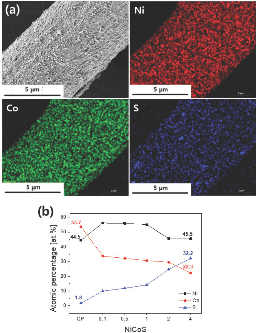
(a) SEM and EDS elemental mapping images of NiCoS-2 and (b) changes in atomic percentages of Ni, Co, and S in NiCoS samples.
이때, 펄스 전기전착을 도입, T off 동안 S의 전구체로 사용되는 thiourea가 전극으로 충분히 공급될 수 있는 시간을 제공함으로써 NiCoS 내 S의 함량을 증가시킨 것으로 추측된다. 또 하나 주목할 점은 NiCoS-0.1에서 NiCoS-CP 대비 Co의 함량이 53.7 at%에서 33.8 at%로 약 37% 감소하고, Ni의 함량이 44.5 at%에서 56.2 at%로 26%가량 증가하는 변화가 관찰되었다는 것이다. 높은 전기음성도를 가진 S 때문에 Co-S 보다 H-S의 결합이 매우 강하게 작용하는데, 펄스 전기전착으로 인해 증가된 S의 함량이 Co-S 결합 형성에 영향을 주어 Co의 함량의 감소, Ni의 함량의 증가를 야기했을 것이라 추측할 수 있다[38, 39].
이러한 Ni, Co, 그리고 S의 복합적인 함량 변화가 NiCoS의 표면 형상 변화에도 영향을 준 것으로 보인다. NiS, CoS, NiCoS 등 대부분 S이 첨가된 전기전착 촉매의 경우, S의 전구체가 가장 일반적으로 사용되는 thiourea라고 가정하였을 때, S의 함량을 높이기 위해서 Ni, Co 대비 매우 높은 농도의 S 전구체를 이용한다[11, 19]. 그럼에도 불구하고 NiCoS-CP의 경우와 같이 포함되는 S의 양은 10 at% 이하 수준으로 매우 적은 편이다[40, 41]. 하지만 NiCoS 제작에 펄스 전기전착을 도입함으로써 S 전구체의 농도 조절 없이 NiCoS-4 를 기준으로, 정전위법의 경우보다 18배 이상의 S 함량을 달성했다. 결과적으로 T off의 변화만으로 NiCoS 내의 S 함량을 조절할 수 있었다.
Fig. 4는 전착된 NiCoS의 XRD 패턴이다. 43.2°, 54.2°에 위치한 피크(peak)는 NiCoS의 기판으로 사용된 carbon paper의 회절 피크이다. 이를 제외하면, 다른 피크는 나타나지 않았다. 이를 통해 모든 NiCoS 시료들이 비정질 구조(amorphous structure)를 가지고 있음을 확인할 수 있었으며, 이는 타 문헌의 전기전착 NiCoS의 결과와 동일했다[19, 42]. 즉, 펄스 전기전착이 NiCoS의 결정구조에 큰 영향을 끼치지 않았음을 확인할 수 있었다.

XRD patterns of electrodeposited NiCoS samples.
NiCoS의 HER 활성을 확인하기 위해 1 M PBS 용액에서 LSV를 수행하였다. Fig. 5a와 b는 각각 iR 보정 전후의 LSV 그래프이다. Fig. 5a에서 T off가 증가함에 따라 동일 전류를 얻기 위해 필요한 과전압이 감소함을 확인했다. Fig. 5b의 iR 보정 후 그래프에서도 보정 전과 동일한 경향성을 나타났는데 NiCoS-CP는 −10, −50 mA/cm2에서 각각 271, 373 mV로 가장 큰 과전압을 보였다. HER에서 가장 높은 활성을 보이는 NiCoS-4의 −10, −50 mA/cm2에서 과전압은 각각 262, 285 mV 로, 가장 낮은 과전압을 가졌다. 이러한 경향은 Toff의 증가에 따른 S의 함량 변화와 일치한다. NiCoS의 경우 S 의 전기 음성도가 Ni, Co보다 높아서 수소 흡착 시 활성점으로 작용, 수소 흡착에 필요한 에너지를 낮춰 NiCoS 의 HER 활성을 증가시키는 것으로 알려져 있다[11, 12, 49]. 그뿐만 아니라 S가 촉매의 전기 전도도를 증가시키기 때문에 S의 함량이 제일 높은 NiCoS-4가 높은 HER 활성을 나타낸 것으로 보인다[50]. 이러한 경향성은 타 문헌에서의 결과와 유사했다[11]. NiCoS-4의 HER 활성은 현재까지 보고된 Ni, Co, 그리고 S 기반의 다른 전이금속 기반의 촉매들과 비교하여 뒤떨어지지 않는 HER 활성을 보였으며, 이는 Table 2에 나타내었다.
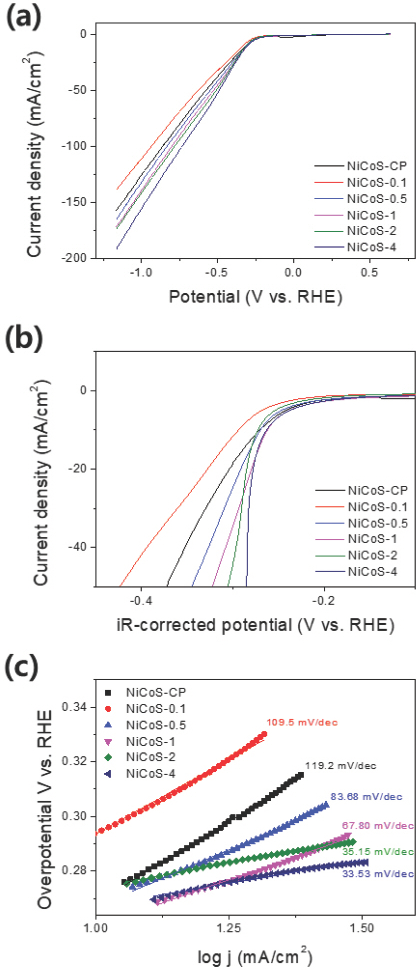
LSV polarization curves of NiCoS-CP, NiCoS-0.1, NiCoS-0.5, NiCoS-1, NiCoS-2, NiCoS-4 (a) before and (b) after iR-correction, (c) corresponding Tafel plots.

Comparison of catalytic parameters of NiCoS-4 with other non-noble-metal HER catalysts in neutra solution

Rs and Rct of NiCoS samples
Tafel 도시를 통해서도 동일한 결과를 얻었다 (Fig. 5c). Tafel 도시에서 기울기는 특정 전기화학 반응에서 전극이 가지고 있는 촉매의 활성을 간접적으로 나타낸다. 따라서 Tafel 기울기가 작을수록 해당 전극이 높은 성능을 가진다고 볼 수 있다 [51, 52]. 전착된 NiCoS 의 Tafel 기울기는 Fig. 5c에 나타내었다. NiCoS-CP 는 119.2 mV/dec으로 가장 큰 기울기를 나타냈으며 NiCoS-0.1, NiCoS-0.5, NiCoS-1, NiCoS-2는 각각 109.5, 83.68, 67.80, 35.15 mV/dec의 기울기를 보였다. 그리고 NiCoS-4의 경우 33.53 mV/dec으로 가장 작은 기울기를 보였다. 즉, T off이 증가할수록 Tafel 기울기가 낮아졌으며, 이는 Fig. 5a와 b에서 나타난 경향과 일치했다. 또한 증가한 S 함량에 따라 Tafel 기울기가 109.5 mV/dec에서 33.53 mV/dec으로 크게 감소하였음을 통해 NiCoS의 HER 메커니즘이 Volmer-Heyrovsky에서 Volmer-Tafel로 바뀌었음을 알 수 있었다[53].
촉매의 표면적은 전기화학 반응이 일어날 수 있는 면적을 의미하기 때문에 넓은 표면적은 좋은 성능의 촉매를 가지기 위한 중요 조건 중에 하나이다. NiCoS의 표면적은 C dl 측정을 이용해 간접적으로 조사하고자 하였으며, C dl 측정은 HER이 일어나지 않는 0~ −0.13 V (vs. Ag/AgCl) 범위에서 CV를 통해 진행하였다. Figs. 6a-e는 각 시료의 CV 그래프이며, Fig. 6f는 CV 주사 속도에 따른 −0.065 V (vs. Ag/AgCl)에서의 용량성 전류밀도(capacitive current density)의 변화 그래프이다. NiCoS-0.1, NiCoS-0.5, NiCoS-1, NiCoS-2, NiCoS-4는 각각 0.39, 0.54, 0.60, 0.68, 0.94 mF/cm2의 정전 용량(capacitance)을 나타냈다. 이로부터 T off가 증가할수록 NiCoS가 넓은 표면적을 가짐을 확인할 수 있었다. 이러한 경향성은 Fig. 2에서 T off에 따른 재핵화 현상과 관련이 있을 것이라고 추측할 수 있다. 재핵화로 인해 촉매의 크기 성장보다는 작은 크기의 촉매가 더 많이 형성되고, 이는 표면적의 증가를 야기하였다. 이에 따라 T off이 가장 긴 NiCoS-4에서 가장 작은 촉매의 크기가 형성, 가장 큰 정전 용량을 가지게 되었을 것으로 예측할 수 있다.
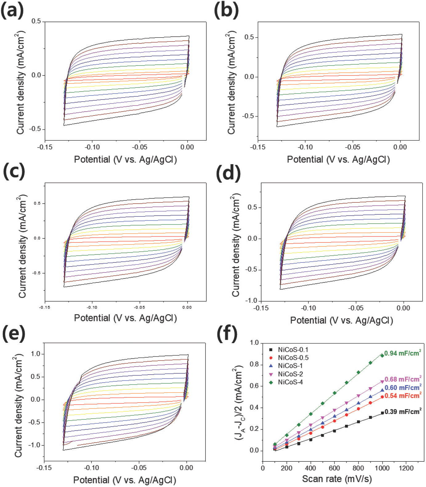
CV curves of (a) NiCoS-0.1, (b) NiCoS-0.5, (c) NiCoS-1, (d) NiCoS-2, (e) NiCoS-4 in 1 M PBS, and (f) C dl data of electrodeposited NiCoS samples determined by electrical double layer charging current density vs. scan rates. The scan rate ranges from 100 to 1000 mV/s (red to black).
촉매의 전하 전달 저항(R ct)를 알아보기 위해 EIS를 수행하였다 (Fig.7). NiCoS의 R s 값은 평균 2.3 Ω 정도로 모든 시료에서 비슷한 저항값을 얻었다. 하지만 측정된 R ct는 시료들 사이에 큰 차이가 존재했다. R ct는 펄스 전기전착 시 T off가 증가할수록 감소하였으며, T off가 가장 긴 NiCoS-4는 4.16 Ω으로 제일 작은 값을 가지고 있었다. R ct는 전극과 반응물질 간의 전하 전달 속도에 영향을 미치는 값으로, 크기가 작을수록 전기화학 반응에 유리함을 의미한다[54, 55]. 이러한 결과는 펄스 전기전착으로 제작된 NiCoS 시료의 HER 활성(과전압)과도 일치하였다. 펄스 전기전착으로 제작된 NiCoS는 T off가 증가할수록 S의 함량과 표면적이 증가하였으며, 이들 요소들이 전하 전달 저항을 감소시켜 HER에 대한 활성 증가에 긍정적인 영향을 미친 것으로 사료된다.
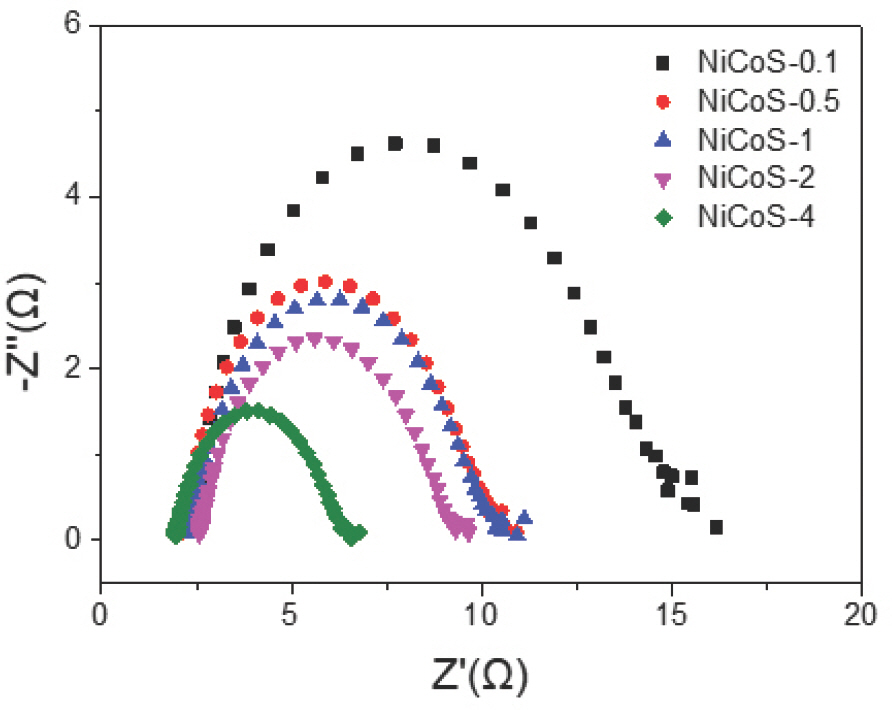
EIS curves (Nyquist plots) of electrodeposited NiCoS samples.
시료들 중에서 HER에 가장 좋은 활성을 보였던 NiCoS-4의 내구성을 평가하였다. 내구성 성능 테스트는 1 M의 PBS 용액에서 −15 mA/cm2의 전류를 가해 10시간 동안 진행했다 (Fig.8). NiCoS-4는 10시간 동안 –0.32 V (vs. RHE)의 전위를 비교적 일정하게 유지하였으며, 이를 통해 NiCoS-4의 내구성이 우수하다는 것을 확인할 수 있었다.

Potential-time curve of NiCoS-4 at −15 mA/cm2 in 1 M PBS.
4. 결론
본 연구에서는 HER의 촉매로 사용되는 NiCoS를 펄스 전기전착으로 제조하고, 펄스 전기전착의 주요 매개변수인 T off가 NiCoS의 HER 활성에 미치는 영향을 조사하였다. T off는 NiCoS의 결정구조에는 큰 영향을 미치지 않았지만, NiCoS의 형태와 조성에는 큰 영향을 미쳤다. T off가 증가함에 따라 NiCoS 내의 황 함량과 표면적 증가가 이루어졌는데, 특히나 황 함량에 있어서 NiCoS-4는 NiCoS-CP와 비교해 18배 증가한 결과를 얻었다. NiCoS에서 황 함량과 표면적의 증가는 낮은 R ct 와 활성점의 증가를 야기하였고, 그에 따라 황 함량과 표면적이 가장 높은 NiCoS-4가 다른 시료보다 높은 HER 활성을 가지고 있었음을 확인하였다. NiCoS-4는 10 mA/cm2를 기준으로 1 M PBS 용액에서 262 mV의 과전압을 나타냈으며, 내구성에서도 우수한 성능을 보였다.
5. 사사
이 성과는 정부(과학기술정보통신부)의 재원으로 한국연구재단의 지원을 받아 수행된 연구임(No. NRF-2022R1F1A1074205).
References
Biography

◉◉임소연
◉ 2016~2021숭실대학교 화학공학과학사
◉ 2021~현재 숭실대학교 대학원 화학공학과 석사과정

◉◉임태호
◉ 2003~2007서울대학교 화학생물공학부학사
◉ 2007~2009서울대학교 화학생물공학부석사
◉ 2009~2013서울대학교 화학생물공학부박사
◉ 2013~2014서울대학교 신소재공동연구소보조연구원
◉ 2014~2015Carnegie MellonUniversity박사후연구원
◉ 2015~2016 UniversityofTexasat Austin박사후연구원
◉ 2016~현재 숭실대학교 화학공학과 조교수